Component Flow
Component Flow Diagram
A Component Flow diagram is the blueprint of an App.
Planning is already building!
A Component Flow diagram is very much like the kind of diagram you might produce if you were (just) planning out an App.
The difference here is that, with Logiak, once you have planned out your App and produced a blueprint, you have also thereby built your App!
Example
Have a look at this example Flow Digram below: this is the blueprint of an App called Test App, and it currently contains four Components, linked together in a Component Flow.
-
The boxes in the Flow Digram each represent a Component.
-
The large green right arrows represent transitions between components.
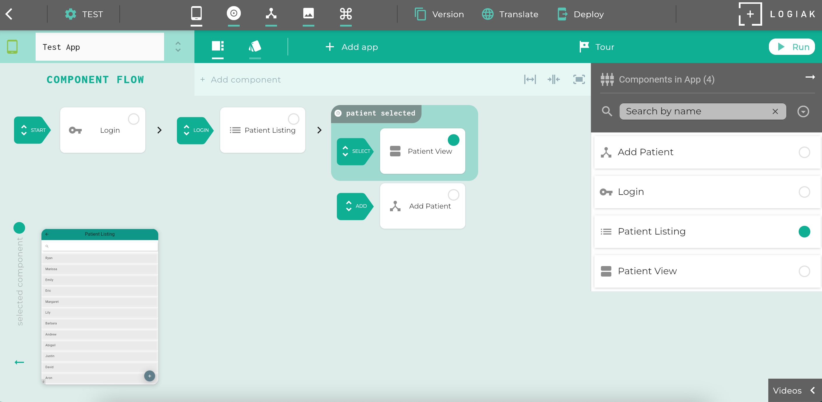
It is to be read left to right.
It starts with a special Transition labelled START.
The START transition is always there, and setting the destination of that transition is how we tell Logiak which Component we want to appear first.
In this example, the START transition takes us to a Login Component.
Login Components have a Login Transition, leaving them, and we define there: which component do we want to appear after the user has logged in…
And so goes the planning/building, deciding which Component to place next..
Expand and Contract
The small right arrows are controls with which you can expand and contract the Flow Diagram.Adding Components
You can add a Component in the Flow in three ways:
- The destination of a - transition.
- or as contained by another Component which is within the Flow.
- or as a navigation element on any Component within the Flow
Here are actions available to modify the Component Flow:
Pinning a component as root
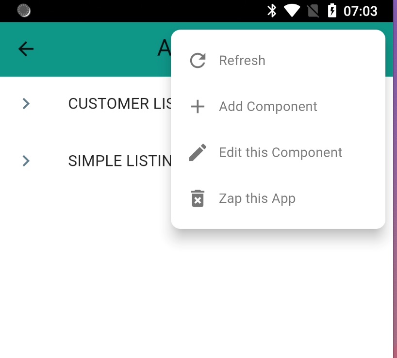
Possible also to edit Component Flow on device
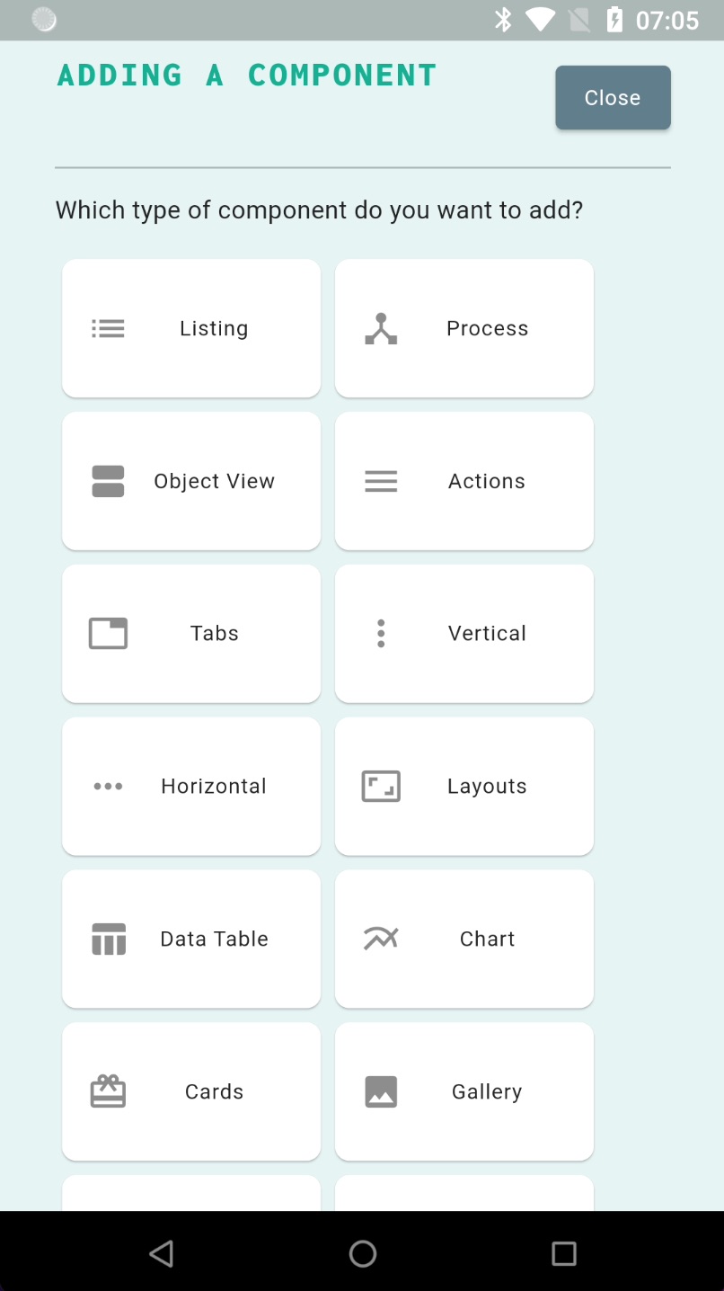
If you have a Deployment which is in Development Mode, you can access Component Flow editing functions from the device - you can add and edit Components.
Feedback
Was this page helpful?
Glad to hear it! Please tell us how we can improve.
Sorry to hear that. Please tell us how we can improve.